House
background
Heat Source
Controls
Loops
Information and
Sources
Home
![]()
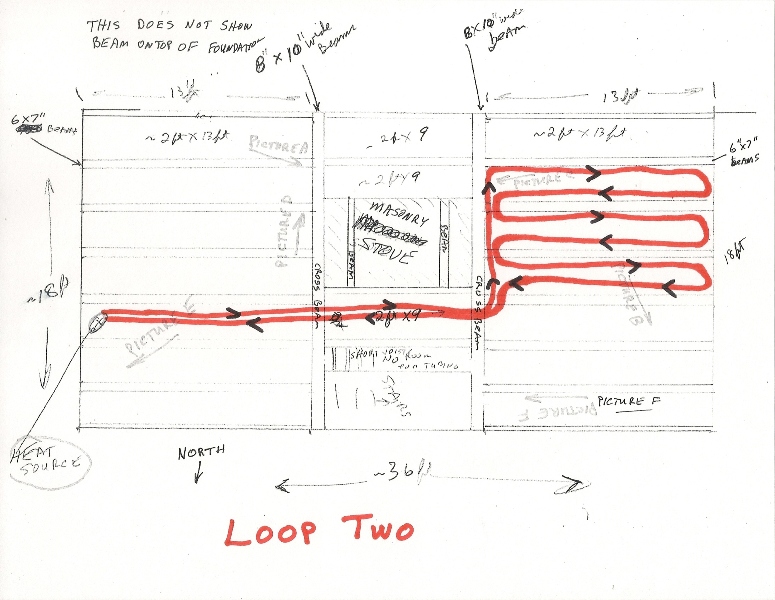
Loop layout
The tubing loops start and return to the same point at the manifolds.
There are 7- 2'x13' spaces between the 6"x7" beams on each end of the house. The joists were spaced approximately 24 inches apart, not 24 on center.
Another big decision was the spacing of the Pex tubing. All kinds of information out there on what spacing should be used. Since most joists are 16" on center usually two runs are placed in that space. Our distance between joists was 24 inches.
For several weeks there were sketches of loops showing up around the house. Back of envelopes, grocery lists, scrap paper, cardboard boxes and almost any other place I could draw. How many loops?, How much drilling?, How long for each?, What temperature would it need?. All questions needing answers to make it work.
Having no experience with Pex tubing I decided to only run two per joist space. My thinking was that if necessary we could come back with another branch and run a single tube between the existing runs that would result in three per space and not have to make the tight bends. That single center run would be one loop covering both west end loops.
With the heat source and controls in place the next step was to circulate the hot water.
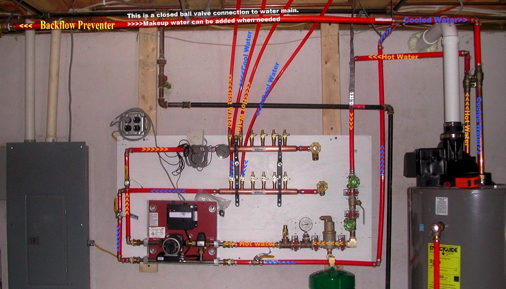
This is a closed system which means the same
water circulates all the time.
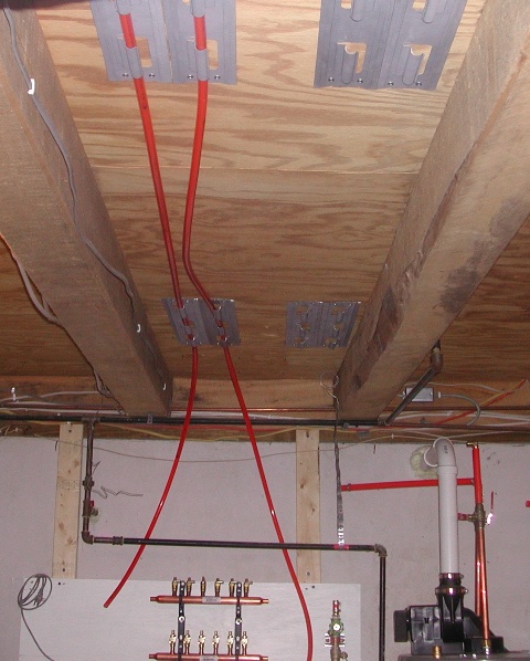
As I said, each loop is one piece of Pex. The above picture was taken when I only had two loops attached. I added arrows to show the path the hot water travels when pumped through the top manifold and where the cooled water returns to the bottom manifold and then to the water heater to be re-heated.
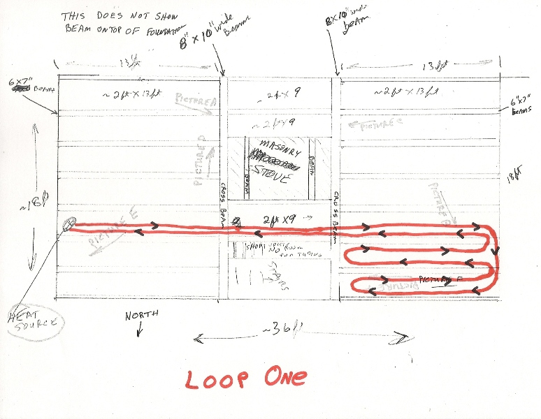
Below is a sketch of loop one. It will cover the first three spaces on North side of living room.
Loop One
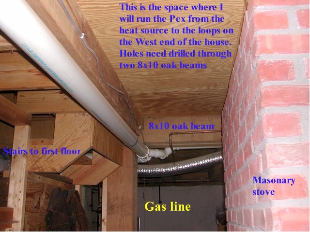
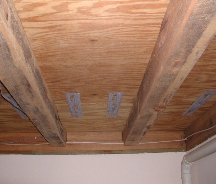
Taken during planning phase and a good shot of
pathway from heat source to loops.
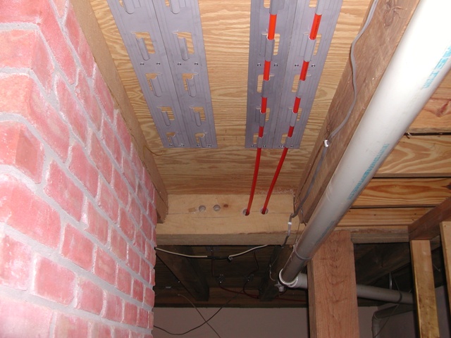
Taken from the other end of same floor section after holes drilled and the first loop tubing attached.
Drilling the holes through the 10 inch seasoned oak beams was a story in itself.
For some reason I did not take any pictures of the operation which is
disappointing because drilling those oak beams was a big issue when deciding if
we did the project at all. Finally concluded minimal drilling could be
done to do the three loops. As you might have noticed we did not do loop
coverage for the entire space. Drilling beams (or not drilling) was part
of that decision. Two branches remain on the manifold and can be added if
needed.
There were several drilling attempts with different bits and drills resulting in broken bits, botched holes and narrowly avoiding broken wrists or drill handles to the side of the head when the oak would grab and stop the bit. Not to mention getting a big drill into a space with water line, electrical line, dryer vent and a drain line.
Again neighbor Jim to the rescue with his 1/2 inch Milwaukee drill and a 1 inch bit 18 inches long. It not only did the job but added another level of danger by holding a really heavy drill while standing on a ladder trying to drill through a 10 oak beam at head height.
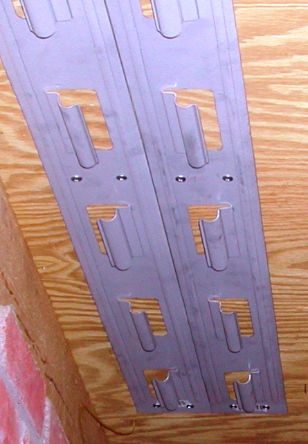
The metal plates are made by Nibco and from Menards and have alternating C shaped channels for easy attaching of the tubing. I decided to use them to do the initial attachment. After deciding the loop layout Jon installed the plates and was able to attach the Pex in the channels by himself. So much easier than fighting coiled Pex while trying to staple up aluminum plates. After the tubing was in place he put aluminum heat transfer plates over the remaining exposed Pex with self drilling metal stud screws. Again easier and much more secure than staples. The aluminum plates will be shown in later pictures.
The picture above shows the three spaces of loop one. The 4 ft. plates were cut in half and used to define the tubing path which made easier attachment as shown below.
This is the 2ft x 13ft space above the
manifolds used to run the Pex to the West end of the
house. The plates are installed for loop one and loop two.

Loop One after insulation installed. This is foil backed foam board with foil face one inch below tubing. I decided to use it instead of the radiant barrier foil or fiberglass batts. It is rigid and installed in a manner that would make taking it down for some future reason easier than taking down stapled up foil or batts. I was thinking about the possibility of adding the middle Pex run between what was just installed.
Loop two

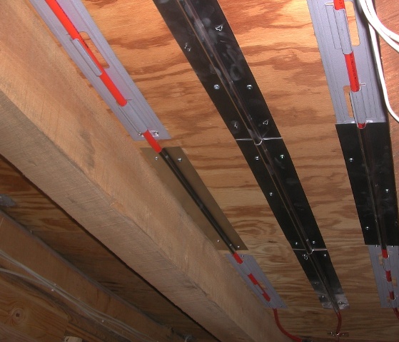
This shows the aluminum heat transfer plates
filling in between the metal plates.
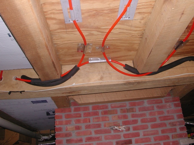
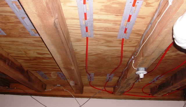
These pictures show how the notches were used in place of drilling holes. Notice to the left above where the tubing comes through the beam. The pipe insulation was added to buffer the tubing contact expansion noise as well as help with heat lose. I have not been too concerned about heat loss into the basement because it also needs heat. So far the temperature has risen about 5 degrees and that is good.
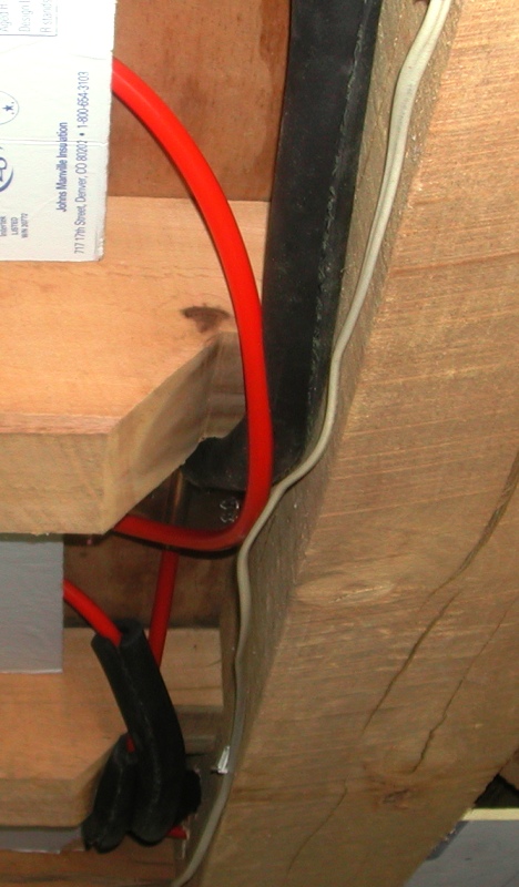
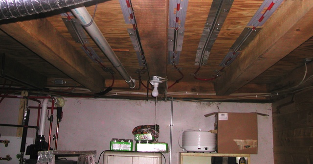
The electrical wire was moved and is not
contacting the Pex as appears in the picture
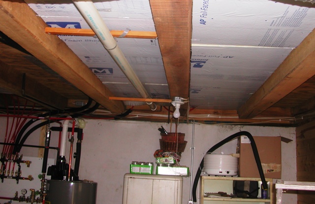
Below is loop 2 after installing foam board
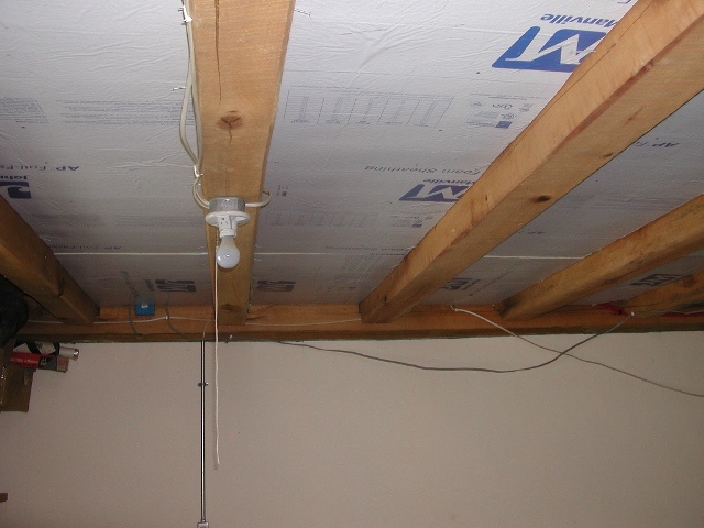
And yes the wires were placed back in neat
manner.
Loop Three
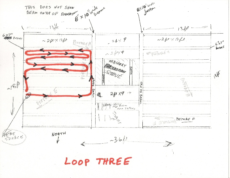
In loop three I decided to try three runs in
the 24 " space.
Probably would have worked everywhere but little late now.
Loop Four
(It is basically a hot supply line and a cool water return line for the
radiator)
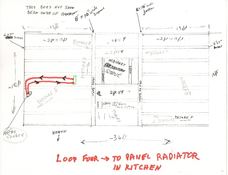
When researching the many ways to use hot water to heat a house there
was a world out there using panel radiators or baseboard units. I wanted
to try a radiator because, unlike the tubing under the floor, the radiator
starts giving off heat into the room almost as soon as the pump starts. In
this install it is only a few feet from the heat source so it reaches hot water
temperature within a few minutes.
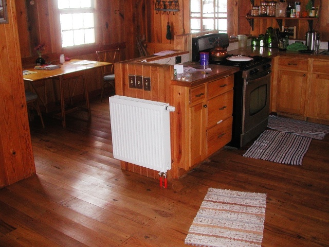
Placement of the radiator was another dilemma. I said before there is an
oak beam sitting on top of the foundation and the reason for not cutting forced
air registers in the floor became the same issue when considering the location
of the radiator. Drilling holes straight down for the Pex hookup would
result in hitting the beam on top of the foundation. Not a pathway that
would work. Drilling out in the floor past the beam would require
two elbows and pipe 6 inches out in the room. Cutting a big notch
out of the beam in the basement would have worked but a lot of work requiring
that big drill at head height again or a chainsaw. Both choices not
acceptable to me.
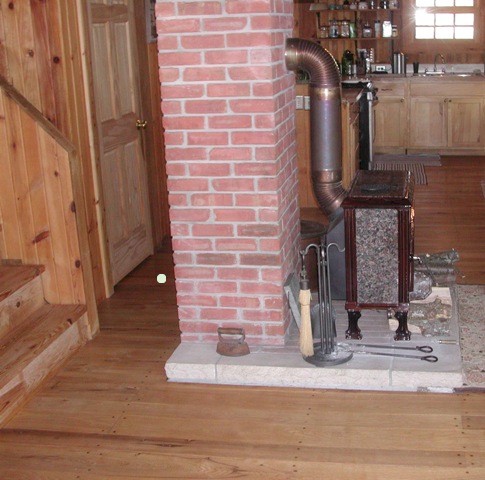
One solution was to put it in the interior of the house away from an outside wall. Several places could have been used but not all ideal. The location chosen was in the kitchen area as shown. Logic being that you could back up to it while drinking your morning coffee waiting for the fire to get going in the stove. They have acknowledged it was a great choice and does work with the morning coffee and a great hand warmer after coming in from outside.
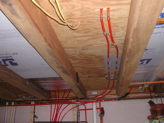
I did buy white pipe covers instead of leaving
the red pipes showing.
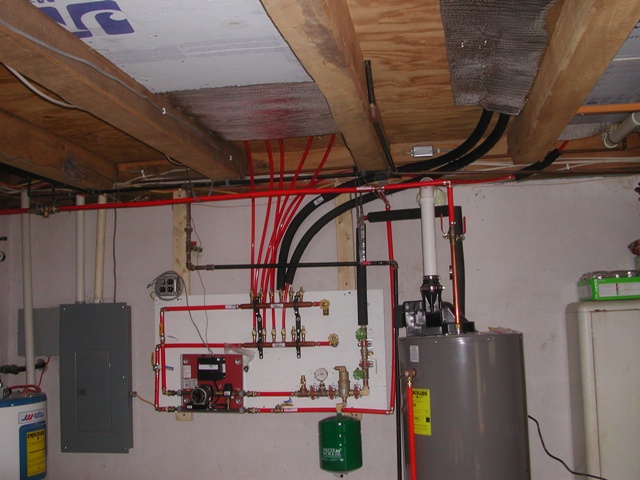
The picture below shows the four branches attached and in operation. I insulated the tubing to the radiator for maximum heat output. The heat generated from the exposed Pex on the other branches will accomplish the goal of keeping all the water lines and house plumbing protected if wood burning stove is not fired or no one is home for several days during severe cold weather.
Thermostat and sensor
Everything is working and now the task becomes finding the proper control for the desired house temperature. The thermostat can be used to control the system based upon air temperature as most heating systems use or use a probe to sense the floor temperature. I decided to use the floor sensor and that is worthy of another discussion for another time. One website has 5 methods for probe placement.

This is the only picture I had of testing the probe in the section
between the cross beams and masonry stove and stairs.
Below is a picture taken earlier but added here to give relative location. These
pictures actually show both ends of the same metal plates.
The white dot in front of the basement door shows approximate location
of floor sensor. The sensor is in a slot cut in the plywood subfloor and just under
the main floor. As suggested in one article it is about 2 inches away from
the end of the heat plate as you can see in the picture. The sensor seems
to be working in this location but I assume it will be several weeks with varied
winter weather conditions to find out more results. I will try to do an
update later.
January 27, 2016 update:
The floor sensor was placed in the above location on January 15, 2016. The
past 14 days weather history has three days with a low below 10, four days with
low between 10 and 20 and the other days with low between 20 and 30. The
highs ranged from 13 on January 18 to 51 on January 25 with other days high
temperature in the 20 to 35 range.
Having a fire in the wood burner has been inconsistent so this has been a good test of the radiant. Yesterday was a good example of a cold and windy day with a morning low at the house of 25 and the afternoon high of 39. There had not been a fire in the wood stove since Monday evening. The air temperature in the West end of the living room at 5:00 PM was 61. On some of the colder windy days without a fire it would drop to the high 50's but the floor was nice and warm.
Results are acceptable for this house. I am convinced that if the stairwell had been designed to close off and the windows had insulated coverings the radiant would provide the necessary heat for the first floor without the wood burner .
I also have to say if I wanted to add to this system it would be with radiators. The warm floors are so nice but the radiator really dumps out the heat. A couple more would just get more heat in the room so much faster.
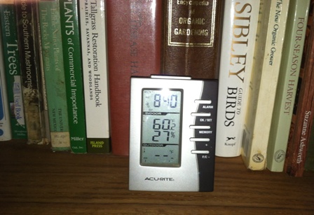
This shows 60 at 8:40 AM Jan 27. Calm wind.
Forgot to add some very important information that is key to results.
The water temperature from heater is only 125º F. and the floor sensor thermostat is set on 75º F. Low temperature discussions talk about 140º water as the norm and boilers usually run water at 180º so raising the water and the floor sensor higher would make results even better.
I cannot end this without acknowledging the local and online companies and the information websites out there where I was able to research and buy materials. There is a lot to sort out depending upon your application.
It was a mixed bag. Some of the good information came from places not selling anything and some selling materials did not provide much more than parts lists. As one person told me: "We are sales clerks not design engineers." Online sales have changed this business as with so many others. I could read about all the parts, check prices and inventory, see reviews from others and order everything online if I had wanted. For my project it was an advantage to buy most locally with my design/build method. Being in the Midwest with Menards also helped. No questions ask when I returned parts to Menards and Lowes I did not need.
Good examples of both were the backflow preventer, the air eliminator, the aluminum heat transfer plates and the brass fittings for my plumbing tree. Menards and Lowes had about 95% of what I needed but the other 5% was required for my system. Menards did not have the brass street elbows I wanted but SupplyHouse did and my order to them for the fittings, backflow preventer and pop off valve arrived in two day. The air eliminator came from PexUniverse because Menards only had one with sweat fitting. Aluminum heat transfer plates were ordered from PexSuperstore because no local supply.
I added a page listing some of those resources.
House background Heat Source Controls Loops Information and Sources
![]()
Home